

IGBT Selection for Commercial Induction Cookers: Voltage Headroom, Short-Circuit Protection, and Resonant Topology
In a half-bridge series-resonant topology, the IGBT sees peak voltage more than twice the bus voltage. With 1350V blocking, 10us short-circuit withstand, and a soft-recovery diode,
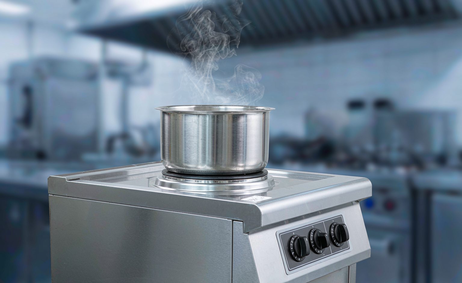
In a half-bridge series-resonant topology, the IGBT sees peak voltage more than twice the bus voltage. With 1350V blocking, 10us short-circuit withstand, and a soft-recovery diode, the HG30T135TPX100 clamps resonant spikes while preserving the window for dry-heat protection to act.
Bottom Line First: How Should You Choose an IGBT for a Commercial Induction Cooker?
If your induction cooker meets the conditions below, a 1350V-class IGBT discrete such as the HG30T135TPX100 is a high-confidence choice:
- Output power above 3.5kW — the half-bridge topology in commercial units exposes the device to high resonant voltage
- Continuous full-power operation — canteens and restaurant kitchens run continuously, placing extreme pressure on thermal design
- Over-temperature dry-heat protection is mandatory — removing the pot leaves the coil unloaded and resonant voltage rises sharply
Conversely, for a household induction cooker below 2kW, a 1200V-class device with a proven topology is sufficient — no need to pay for 1350V headroom.
Three Real Engineering Conflicts in Commercial Induction Cookers
Working on commercial induction-cooker electronics never presents a single problem:
- Resonant voltage spikes far exceed the bus voltage. In a half-bridge series-resonant topology, the peak voltage across the IGBT can exceed twice the bus voltage — insufficient rating leads directly to device destruction.
- Dry-heat operation is inevitable. Kitchen staff removing the pot is routine; the coil then runs unloaded with elevated Q, resonant voltage surges, and the protection circuit has only microseconds to act.
- Continuous high-power operation drives junction temperature steadily upward. Commercial units run ten hours or more per day, leaving the device almost no recovery time.
The HG30T135TPX100 was designed around exactly these three conflicts.
Five Key Characteristics of the HG30T135TPX100
1. Low Saturation Voltage: 2.3V @25℃ / 2.8V @150℃
Saturation voltage is 2.3V at Tj=25℃ and 2.8V at Tj=150℃. Lower conduction loss means less self-heating, allowing higher power within the same thermal budget. This converts directly into product competitiveness — between two 5kW units, the one that runs cooler can be smaller and quieter.
2. Low Switching Losses: Eon=3.0mJ / Eoff=1.5mJ
Turn-on loss of 3.0mJ and turn-off loss of 1.5mJ (at 25℃). Induction cookers operate at 20–40kHz, where switching loss is a significant share of total loss, so optimizing switching behavior directly relieves thermal pressure.
3. High Short-Circuit Withstand: tsc = 10µs
During abnormalities such as dry heating, the device provides 10µs of short-circuit withstand time — enough for the protection circuit to act and shut down the drive, preventing catastrophic failure. Those 10µs are the only window the protection circuit has, making this the critical reliability parameter for commercial induction cookers.
4. Fast Soft-Recovery Diode (FRD)
The integrated diode has low reverse recovery charge Qrr, effectively suppressing turn-off spikes and oscillation. The value of soft recovery: a gentler recovery process means lower di/dt, less EMI, and reduced dependence on snubber circuitry.
5. Low Thermal Resistance: Rth(j-c) = 0.36K/W
Junction-to-case thermal resistance of 0.36K/W gives excellent heat conduction, slowing junction temperature rise and permitting prolonged high-temperature operation with longer service life.
Key Parameters at a Glance
| Parameter | Value | Test Condition |
|---|---|---|
| Blocking voltage VCES | 1350V | — |
| Saturation voltage VCE(sat) | 2.3V | Tj=25℃ |
| Saturation voltage VCE(sat) | 2.8V | Tj=150℃ |
| Turn-on loss Eon | 3.0mJ | 25℃ |
| Turn-off loss Eoff | 1.5mJ | 25℃ |
| Short-circuit withstand tsc | 10µs | — |
| Thermal resistance Rth(j-c) | 0.36K/W | — |
| Reverse recovery charge Qrr | Low (soft recovery) | Integrated FRD |
| Package | TO-3PN | |
Working Principle: The IGBT in a Half-Bridge Series-Resonant Topology
Commercial induction cookers widely use the half-bridge series-resonant topology, operating in four steps:
- Rectification and filtering. Mains is rectified through a bridge rectifier and smoothed by high-capacity capacitors to obtain a clean DC voltage Vdc.
- High-frequency inversion. Two HG30T135TPX100 devices conduct alternately (complementary switching) under drive-signal control, converting DC into square-wave AC.
- LC resonance. The square-wave voltage is applied to a series-resonant loop formed by the excitation coil (equivalent inductance L) and the resonant capacitor (C). As the switching frequency approaches resonance, high-amplitude high-frequency current flows in the coil, creating a strong alternating magnetic field for heating.
- Power regulation. Fine adjustment of the switching frequency (via pulse width) drives the loop away from or toward resonance, giving stepless output-power control.
The critical constraint of this topology: at resonance, the voltage across the coil is far higher than the bus voltage, so device blocking voltage must have ample margin. This is precisely why 1350V-class devices have become mainstream in commercial units.
Application Case: Power Stage Design for a 5kW Commercial Induction Cooker
Design targets: 20–40kHz operating frequency, continuous full-power operation, dry-heat protection capability.
Measured results:
- Overall efficiency maintained above 90% at rated power
- During dry-heat testing, the protection circuit acted reliably within the short-circuit withstand window with no device damage
- After 8 hours of continuous full-power operation, junction temperature stabilized within the safe range with no derating triggered
- Turn-off voltage spikes effectively suppressed, allowing the snubber circuit to be simplified
The snubber point is often overlooked: the low di/dt delivered by the soft-recovery diode lets designers use a smaller snubber capacitor — saving cost and reducing power-board volume.
Two Points Most Often Overlooked During Selection
1. Short-Circuit Withstand Must Match Protection-Circuit Response Time
10µs of withstand capability sounds generous, but actual protection response time comprises current-sampling delay, comparator delay, and gate turn-off delay. If those three together exceed 10µs, no amount of device tolerance will help. Measure the total time from fault inception to gate voltage reaching zero, and keep at least 30% margin.
2. Power-Up Sequencing and Resonant Capacitor Matching
At power-up, the resonant capacitor is uncharged, so the first switching event produces a large inrush current. If the drive timing is poorly designed — for example, both devices conduct simultaneously for too long — the device can be destroyed at the moment of startup. We recommend examining the VCE and IC waveforms for the first three switching cycles with an oscilloscope during prototyping.
Frequently Asked Questions
Why use a 1350V device rather than 1200V in a commercial cooker?
It depends on bus voltage and topology. Commercial units typically run a higher bus voltage to raise power density, and the peak voltage across the device at resonance can exceed twice the bus voltage. A 1200V device lacks sufficient margin in some operating conditions, whereas a 1350V device provides comfortable blocking headroom at the same bus voltage. The selection principle: determine the voltage class from maximum bus voltage × resonant factor × safety factor (1.3 or higher is recommended).
What is the practical value of soft-recovery behavior?
Two direct benefits. First, lower turn-off spikes — a gentler recovery means lower di/dt, smaller voltage spikes from parasitic inductance, and reduced actual voltage stress on the device. Second, reduced EMI — weaker high-frequency oscillation means both conducted and radiated interference are lower, making certification testing easier and allowing fewer snubber components.
The unit runs hot during continuous operation — is it the device or the cooling?
Work through it in steps. First check whether the actual operating frequency has drifted away from resonance — the further it drifts, the larger the hard-switching component and the higher the loss. Then verify that junction temperature is within a reasonable range. If junction temperature is normal but the exterior is hot, it is a heatsink-structure issue; if junction temperature itself is high, recalculate device losses. A low-thermal-resistance device (0.36K/W) relaxes thermal design margin, but only if the loss itself has not inflated abnormally.
Summary
The HG30T135TPX100 is positioned as an IGBT discrete solution for the half-bridge resonant topology of commercial induction cookers, balancing voltage headroom, low loss, and short-circuit protection. Its core strength is combining 1350V blocking voltage, 10µs short-circuit withstand, and a soft-recovery diode — clamping resonant voltage spikes while preserving a window for dry-heat protection to act. For commercial kitchens that must run continuously, reliability matters more than peak efficiency.
Need a power-stage selection study for a specific model? Tell us your output power, bus voltage, and cooling method, and we will recommend a matching device combination.